
ردیوسینگ ولو رکسروت
Bosch Rexroth اصلی
نصب زیر شیر هیدرولیک
تقسیم بندی در 5 فشار مختلف
طراحی بر اساس ISO 4401-03-02-0-05
استعلام قیمت
ردیوسینگ ولو رکسروت
Bosch Rexroth اصلی
نصب زیر شیر هیدرولیک
تقسیم بندی در 5 فشار مختلف
طراحی بر اساس ISO 4401-03-02-0-05
لطفا برای آگاهی از قیمت و دریافت فاکتور، استعلام قیمت برای این کالا را ارسال کنید. همکاران ما پس از بررسی، فاکتور فروش را برای شما صادر و از طریق پیامک به شما اطلاع خواهند داد.

ردیوسینگ رکسروت ZDR
ردیوسینگ ZDR10 بوش رکسروت Bosch Rexroth
بررسی فنی و عملکرد ردیوسینگ رکسروت ZDR10
تامین و فروش شیرهای کنترل فشار ساده و پیلوت دار ساخت شرکت Rexroth آلمان
شیرهای ردیوسینگ رکسروت فشار بالایی را در ورودی دریافت میکنند و فشار کمتر و تنظیم شده ای را در خروجی تحویل میدهند . این ولو هیدرولیکی بدون سوپاپ میباشد .
ردیوسینگ ولو در مسیر و خطوط هیدرولیک بین پمپ و جک ( سیلندر ) هیدرولیک و یا هیدروموتور قرار میگیرد .
در حالت غیرفعال داری مسیر باز هستند و با افزایش فشار مسیر را میبندند .
برای دریافت مشاوره و نحوه نصب و همچنین آگاهی از قیمت و خرید ردیوسینگ ولوهای Rexroth رکسروت با کارشناسان فنی و مالی ما در فروشگاه هیدرولیک هیدشاپ تماس بگیرید .
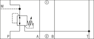
Version P YM
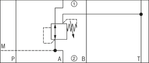
Version A YM
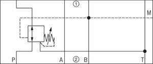
Version B YM
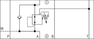
Version A Y
▶▶ Sandwich plate valve
▶▶ Porting pattern according to ISO 4401-03-02-0-05 (with or without locating hole)
▶▶ 4 pressure ratings
▶▶ 4 adjustment types, optionally:
–– Rotary knob
–– Bushing with hexagon and protective cap
–– Lockable rotary knob with scale
–– Rotary knob with scale
▶▶ Pressure reduction in channel A, B or channel P
▶▶ Check valve, optional (version “A” only)
▶▶ Corrosion-protected design
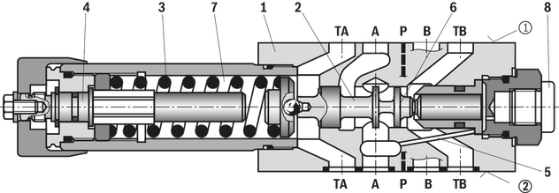
ساختار ردیوسینگ رکسروت ZDR10
The valve type ZDR is a direct operated pressure reducing valve in sandwich plate design with pressure limitation of the secondary circuit.
It is used to reduce the system pressure.
The pressure reducing valve basically comprises housing (1), control spool (2), compression spring (3), adjustment type (4) and an optional check valve.
The secondary pressure is set via the adjustment type (4). Version “A” The valve is open in initial position. Hydraulic fluid can flow from channel A① to channel A② without restrictions.
The pressure in channel A② is simultaneously applied via the control line (5) at the piston area opposite the compression spring (3). If the pressure in channel A② exceeds the value set at the compression spring (3), the control spool (2) is pushed against the compression spring (3) to control position and keeps the set pressure in channel A② at a constant level. Control signal and pilot oil are supplied internally via the control line (5) from channel A②.
If the pressure in channel A② increases further due to an external force effect at the actuator, it pushes the control spool (2) even further against the compression spring (3).
In this way, channel A② is connected to the tank via the control edge (9) at the control spool (2) and the housing (1). So much hydraulic fluid is discharged into the tank that the pressure does not increase any further. The leakage oil drain from the spring chamber (7) is always effected externally via the bore (6) and channel T (Y). A pressure gauge connection (8) allows for the control of the secondary pressure at the valve. A check valve can be used for free flow back from channel A② to A① with version “A”. Versions “P” and “B” With version “P”, the pressure reduction is effected in channel P①. Control signal and pilot oil are supplied internally from channel P①. With version “B”, the pressure is reduced in channel P①; but the pilot oil is extracted from channel B.
 ادامه مطلب
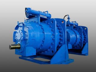
در این مقاله، با بررسی نکات کلیدی در فرآیند ساخت گیربکسهای قدرتی، از تحلیل نیازهای صنعتی تا انتخاب مواد مناسب و روشهای تولید، به شما کمک میکنیم تا با اصو ...
 ادامه مطلب
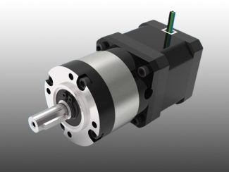
اگر به دنبال راهی برای صرفهجویی در هزینهها یا عملکرد بهینه و پایدار هستید و به دنبال پاسخ برای خرید گیربکس خورشیدی استوک یا نو میگردید، دعوت میکنیم مطال ...
 ادامه مطلب
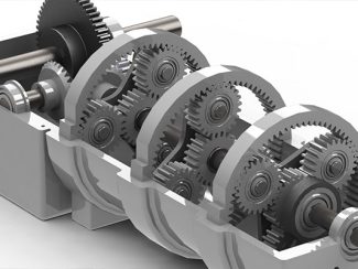
جالب است بدانید که این تکنولوژی قادر به کاهش سرعت تا 1:1000 است و گشتاور را به طرز چشمگیری افزایش میدهد. در این مقاله، با ساختار، مزایا، و کاربردهای موتور ...
 ادامه مطلب
انوع گیربکسهای خورشیدی با قابلیت تنظیم نسبت انتقال، سرعت و گشتاور را بهطور دقیق کنترل میکنند و عملکرد بهینهای در شرایط مختلف کاری ارائه میدهند.در این ...
 ادامه مطلب
معایب گیربکس خورشیدی مانند پیچیدگی تعمیرات، سایش زیاد قطعات، حساسیت به شوکهای مکانیکی و هزینه بالای نگهداری از جمله مواردی هستند که باید پیش از خرید یا است ...
 ادامه مطلب
به همین دلیل، تشخیص خرابی گیربکس خورشیدی و انجام عیبیابی دقیق، میتواند جلوی خسارتهای بزرگ و هزینههای اضافی را بگیرد. این فرآیند به مدیران فنی کمک میکن ...
 ادامه مطلب
گیربکسهای خورشیدی، بهعنوان یکی از پیچیدهترین و کارآمدترین سیستمهای انتقال نیرو، جایگاه ویژهای در صنایع پیشرفته یافتهاند. ساختار منحصر بهفرد آنها، مت ...
 ادامه مطلب
از سال 1830 گیربکسها بهعنوان اجزا مهم در انتقال قدرت مکانیکی در صنعت مورداستفاده قرار میگیرند. این دستگاهها نقش مهمی در کنترل سرعت و گشتاور ماشینآلات ص ...
 ادامه مطلب
نصب و تنظیم گیربکس خورشیدی، اصول مهمی دارد که رعایت آنها فعالیت سالم گیربکس را تضمین میکند. نکات مهم در تنظیم نصب و گیربکس خورشیدی در دستگاههای صنعتی ر ...
 ادامه مطلب
برندهای آلمانی، چینی و ایتالیایی انواع گیربکس خورشیدی را تولید میکنند که هرکدام مشخصات و ویژگیهای خاصی دارند. برای آشنایی با 6 مورد از بهترین برندهای گیرب ...
 ادامه مطلب
موتورهای هیدرولیکی و الکترولیکی، در ترکیب با گیربکسهای خورشیدی برای امور صنعتی استفاده میشوند. در این مقاله به بررسی انواع موتور گیربکس خورشیدی میپردازیم.
 ادامه مطلب
آیا تاکنون تمایزات و تفاوت گیربکس خورشیدی و حلزونی درگیری ذهن شما بوده است؟ در این مقاله، به بررسی این دو نوع گیربکس خواهیم پرداخت و 5 تفاوت مهم با یکدیگر ...
با ما در ارتباط باشید همکاران ما پاسخگوی سوالات شما هستند.
لطفا برای آگاهی از قیمت و دریافت فاکتور، فرم استعلام این کالا را ارسال نمایید.
هنوز بررسیای ثبت نشده است.